
Grating Solver Development Company
Genetic Algorithm Optimization of Sawtooth Profile Grating:
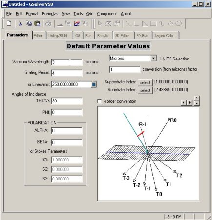
This example considers a sawtooth profile, such as might be cut by a DPT (diamond point turing) machine, in ZnSe. The problem is to find the optimal sawtooth profile (depth and period) to maximize transmission in the -1T order (-i order convention box on Parameters tab unchecked) for 3 micron wavelength, TE polarization, and for 30° incident light.
- Open a new grating editor window
- Change the wavelength to 3 and the substrate material to Herzberger: ZnSe(IRTR-4) and check the Lambda change update box. (This tells GSolver to update the index of refraction if the wavelength changes.)
- Change Theta to 30
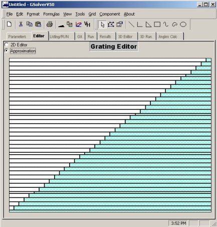
- From the Editor tab, change the canvas properties (Edit Canvas Properties) so that Canvas height is 2. This allows for grating structures that are 2x the grating period, creating an approximation with a large number of layers for finer resolution.
- On the Editor tab, select the Custom Profile tool (black triangle)
- Select the General Sawtooth form, and change the angles to 35 and 90. Click OK.
- Select the newly created object and set its properties to Herzberger:ZnSe(IRTR-4). This should be the default if the substrate material was set.
- Select the shape and assure it is moved all the way to the bottom of the canvas. Then grab the top, center handle and stretch the shape so that it's height is 19 units (this equals 1.9*4 = 7.6 microns)
- Click the Approximation button
- Click the GA tab and Populate the grid
- Click the Options button and enter the goal as -1T 1 1 (-1T order, DE of 1, weight of 1). Click Add, then click OK.
- In cell B7 enter the following formula =if(f5>2&&f5<5,f5,4)
- This constrains the DE algorithm to only allow periods between 2 and 5 microns, and uses 4 microns as the default.
- Change D5 to 2 and E5 to 5
- Click the menu item Grid Thickness Formula, select All and enter the formula =if(f6>0&&f6<.2,f6,.1)
- This allows for a maximum thickness of 8 and a minimum of 0. Note there are 40 layers in the approximation.
- Set B10 (orders retained) to 8
- Set D6 to 0 and E6 to .2
- Click RUN GA
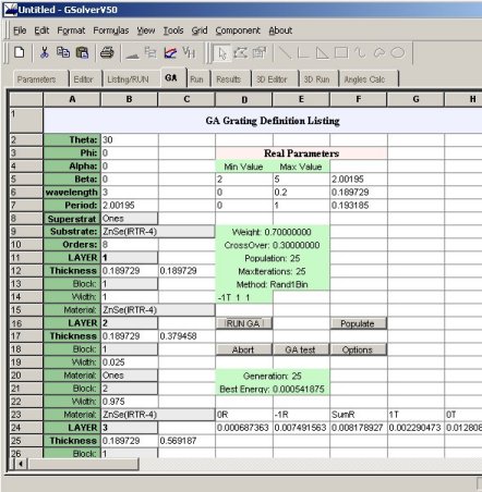
While the GA is running, the current generation is displayed together with the best merit function value. A value of 0 indicates that the goals were met perfectly.
For this example, a period of around 2.0, a total thickness of about 7.6, and an -1T order with approximately 96.9% efficiency are typical.
Change the mode settings under GA Options to examine the behavior of different DE evaluation schedules.
Following is a modification to the above example to find the best grating for simultaneously maximizing transmission, in the 1T and -1T, for thickness, period and angle of incidence. The best such configuration will have 1T = -1T = 0.5.
- Enter the following in B2 =if(F7>0&&F7<80,F7,40)
- Enter 0 in D7 and 80 in E7
- Change the goals on the Options dialog to 1T 0.5 1 and -1T 0.5 1
- Click RUN GA
A typical run may result in Theta = 2., Period = 2.7 and thickness = 2.7 with 1T = 42.% and -1T = 47%.